
Quick answer: A forged wheel drawing should define the mounting interface, rim dimensions, brake-clearance envelope, load and test scope, material, finish, marking and revision status. Before signing it, check that the drawing matches the exact vehicle, axle and commercial SKU. A visually attractive rendering is not a production specification.
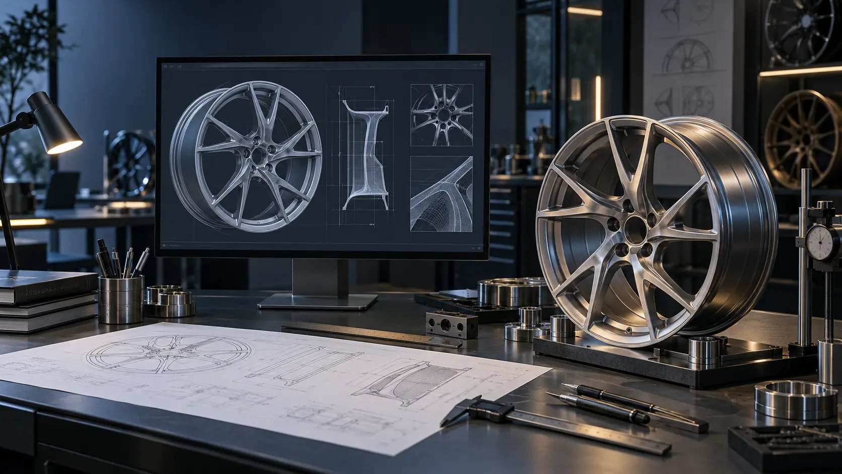
Rendering, Fitment Sheet and Production Drawing Are Different
| Document | Main purpose | What it cannot replace |
|---|---|---|
| Style rendering | Confirms the visual direction, spoke family, color and logo placement | Dimensional fitment and engineering approval |
| Fitment/specification sheet | Collects vehicle, wheel, tire and commercial inputs | A controlled manufacturing drawing with tolerances |
| 2D production drawing | Defines critical sections, interfaces, dimensions, tolerances and markings | A physical sample or applicable validation evidence |
| 3D CAD model | Controls the full wheel geometry and clearance surfaces | The signed revision, material and inspection requirements |
| Inspection report | Records selected measured results for a produced wheel | Proof that every unlisted requirement or market rule is satisfied |
Read the Title Block First
The title block controls which wheel you are approving. It should identify the drawing number, wheel or project code, revision, date, units, projection method, material or referenced specification and approval status. If the email says “Rev C” but the attached PDF says “Rev B,” stop the approval until the conflict is resolved.
- Part number or SKU: should map to the quotation, sample and packaging label.
- Revision: should change whenever an approved dimension, design feature, finish or marking changes.
- Units: millimeters and inches must not be mixed without clear conversion.
- General tolerances: should apply only where a specific tolerance is not shown.
- Approval signatures or record: identify who accepted the design and when.
Mounting Interface: The Highest-Priority Dimensions
| Drawing area | What to verify | Buyer evidence |
|---|---|---|
| PCD and hole count | Exact bolt circle and number of fasteners | OEM data or controlled measurement |
| Center bore | Hub-centric diameter, tolerance and chamfer | Hub specification or measurement |
| Mounting pad | Pad position, diameter, flatness and contact area | Vehicle hub and brake geometry |
| Lug seat | Seat type, angle/profile, hole diameter and hardware | Approved bolt/nut specification |
| Offset/backspacing | ET sign and value, rim width reference and resulting position | Fitment calculation and vehicle clearances |
| Valve/TPMS | Hole location, angle and sensor clearance | Specified valve and sensor hardware |
Rim, Tire and Brake-Clearance Sections
Check the bead-seat diameter, nominal width, flange profile, drop center and inner-barrel envelope. The drawing should distinguish nominal wheel size from actual measured geometry. For a large brake package, a simple caliper diameter is not enough: the spoke back profile, mounting-pad thickness and inner barrel must clear the complete caliper envelope with the agreed margin.
Use a verified brake template, 3D scan or approved caliper model when available. A screenshot from an online listing is not controlled fitment data. The offset calculator helps buyers understand wheel position, but it does not calculate spoke-to-caliper clearance.
Material, Load, Test and Marking Notes
The drawing or linked specification should state the material and condition, target wheel load or application, required test or approval scope, permanent markings and traceability method. Do not accept a generic certificate filename as proof. Match the report or registration to the drawing number, size, load, design family and intended market.
Finish and Branding Details
- Finish stack or approved color/texture reference
- Machined, brushed, polished, painted, anodized or powder-coated areas
- Masking of mounting faces, lug seats, threads and sealing interfaces
- Logo placement, center-cap artwork, engraving depth or marking method
- Visible-surface acceptance standard and approved sample reference
- Packaging label and SKU linkage to the drawing revision
Drawing Approval Checklist
- Match the part number, vehicle, axle and quotation line.
- Confirm diameter, width, PCD, center bore and offset.
- Confirm lug-seat geometry, fastener and TPMS/valve details.
- Review inner and outer clearance against suspension, fender, tire and brake data.
- Confirm load target, required tests, market documents and permanent markings.
- Confirm material, wheel mass target and any controlled manufacturing notes.
- Approve finish, color, logo, center cap and packaging references separately where needed.
- Check the revision and keep the signed PDF/CAD approval with the purchase order.
- Require written approval for any later deviation or substitution.
Red Flags Before You Sign
- The title block has no revision or the filename is the only revision control.
- Offset is shown without wheel width or the ET sign is unclear.
- A generic 5×112 label replaces the exact vehicle and brake information.
- The drawing shows style views but no mounting section or inner-barrel profile.
- A certificate is mentioned but no report/registration scope can be matched to the SKU.
- Finish and logo approvals are buried in chat messages rather than controlled references.
- The supplier requests production approval while open questions remain in the drawing.
Review the full forged wheel fitment guide before drawing sign-off. The forged wheel program page explains the specification-first workflow, and the project hub shows how design, sample and production stages connect.
Frequently Asked Questions
Can I approve a forged wheel from a 3D rendering?
No. A rendering can approve style direction, but production requires controlled dimensions, interfaces, material, finish, revision and applicable engineering requirements.
What does ET mean on a wheel drawing?
ET is the signed offset in millimeters between the wheel centerline and mounting face. Read it together with rim width, because the same ET on different widths produces different inner and outer positions.
Should the drawing include the vehicle name?
Yes, for a vehicle-specific project the application and axle position should be linked to the part number. Chassis code, trim and brake package are more reliable than a model name alone.
Send a Drawing or Build a Specification From Vehicle Data
Share the vehicle, axle, current/OE wheel reference, target size, PCD, center bore, offset, brake data, design file, finish, quantity and market requirements. We can identify missing inputs before a production drawing is approved.